Vivaldi I Photo Gallery |
|
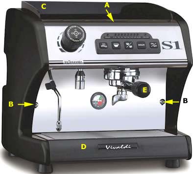 |
Picture 1 - S1 Completely Assembled
- Location of Phillips screw in center front of warming tray. After removal, pull tray straight up and then splash panel C pulls right out.
- These two Phillips screws allow removal of the front metal panel. Since the group sticks down through a hole in this panel, portafilter E must also be removed.
- Splash Panel
- Drip tray
- Portafilter
|
Cooling Fan Found: There is an "L"
shaped chrome piece behind the letters D and E in the above photo. It
bends around the area above the letter H. Also, above the letter
H, but not visible in the photo, is a single screw that is holds this
chrome piece on. Once removed, the cooling fan is right behind it
mounted to the base of the unit. You should be able to hear it running
whenever the Boiler light is flashing. |
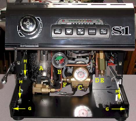
Picture 2 - Front View
- Steam & Hot Water boiler.
- Pressure gauge which shows through the front panel when installed.
- The rotary pump
- 3-way valve outlet
- Adjustable expansion valve for group boiler
- Group Pressure adjustment screw
- Location of two of the six plastic thumb screws that need to be removed in order to pull off the two side panels
- Inside locations of three of the four screws which must be loosened slightly (from the bottom) in order to remove the side panels.
|
 |
Picture 2B - Closer up View of Front
- Street Water inlet to pump
- Pump Outlet which terminates at 3-way valve
- Inlet to 3-way valve.
- Giclar valve which reduces water pressure to steam boiler. Water first passes through black solenoid valve shown below in Picture 5 just left and above the pump motor then flows directly into the steam boiler.
- Full pressure exits the volumetric sensor and enters the group boiler where show in picture 3
- Water from 3-way valve C enters the volumetric sensor.
- Cooling fan shown mounted to bottom chassis and blowing air straight up on to the steam boiler triac heat sink.
|
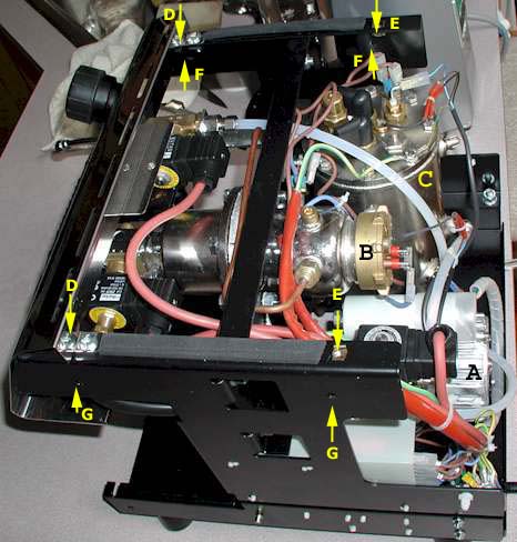 |
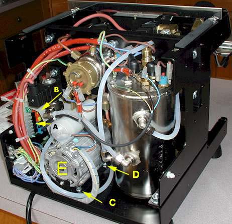
Picture 3 - Top Left View
- Motor that drives the rotary pump.
- Group boiler
- Steam boiler.
- Two Phillips screws hold on the top front panel. When loosened slightly, it is easier to reattach the side panels. Tighten snuggly after the side panels are reattached.
- These are the only screws that attach the back panel. The metal rear panel is held tightly in place by the pressure from the side panels. It is preferable to leave these screws loose until the side panels are on and tightened.
- Inside location of holes for the left side panel's plastic thumb screws.
- Holes where right side plastic thumb screws are screwed through from the inside.
|
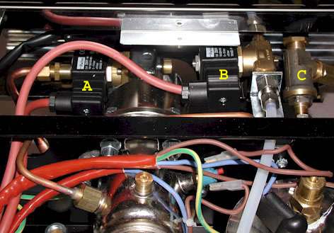 |
Picture 4 - Top back View
- The electronic valve & 3-way for the group
- The electronic valve for the hot water.
- The manual valve for the steam wand.
These can be seen in above photo from a different angle. |
 |
Picture 5 - Full Back View
This straight on photo from the back gives you an idea of the
massive size of the rotary pump motor and the steam boiler.
The clear plastic-enclosed cylinder riding atop the rotary pump motor is
the start up capacitor for the pump motor. Most large motors include this
device to kick start the motor when power is first applied. It also
helps filter the power surge from adding lots of noise on the power
line. |
 |
Picture 6 - Right Rear View
- You can partially see the electronics board mounted vertically on the left side panel.
- It is covered by a gray plastic splash panel
to protect it from water damage. Whenever the boiler turns on you can
here a cooling fan turn on. The sounds appears to come from the area of
the electronics board under the gray plastic splash panel.
- Rear motor mount
- Front motor mount
- Motor which drives rotary pump.
|