 |
LaSpaziale S1 Vivaldi I Website
|
Motor Mount R&RRead the instructions on this page thoroughly. If you feel confident in your mechanical ability to perform these steps, THEN call Chris Coffee Service (assuming you purchased your S1 there and your serial number is lower than 252263) and request a new set of motor mounts. Owners with serial numbers lower than 252263 have the original motor mounts and can DRASTICALLY quiet their machines by requesting a set of upgraded motor mounts and installing them as shown below. This is the definitive quieting solution. It should make any other steps previously discussed unnecessary. If your serial number is 252263 or above you already have the new motor mounts.
|
|
|
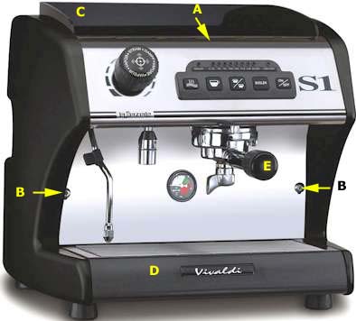
Picture 1 - Remove Warming Tray Cover, front metal panel, portafilter, splash panel, and drip tray.
|
|
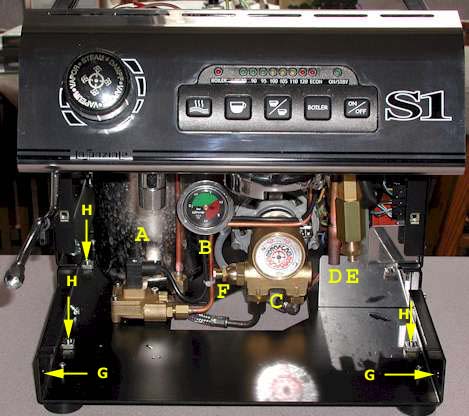
Picture 2 - remove Side Panels Note: You can get by with only removing the right side panel if you wish. However, taking them both off gives to a better chance to ensure that everything is snug and tight when you reassemble. There are three black plastic thumb screws that must be removed on each side and two large Phillips screws that must be loosened on the bottom of the chassis on each side to allow removal of both side panels. 1) Location of the front two of the six plastic thumb screws (G) that need to be removed in order to pull off the two side panels. Location of the other four thumb screws required to remove both side panels shown in the next photo below. 2) Inside locations H) of three of the four screws which must be loosened slightly (from the bottom) in order to remove the side panels. 3) There is an "L" shaped chrome piece behind the letters (D) and (E) in the above photo. It bends around the area above the letter (H). Also, above the letter (H), but not visible in the photo, is a single screw that holds this chrome piece on. Remove it. |
|
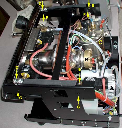
Picture 3 - Complete Side Panel Removal and Rear Panel Removal 1) Inside location of holes (G) for the left side panel's plastic thumb screws. 2) Holes (F) where right side plastic thumb screws are screwed through from the inside. 3) These are the only screws (E) that attach the back panel. Remove these two screws and remove the back panel |
|
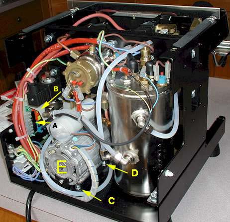
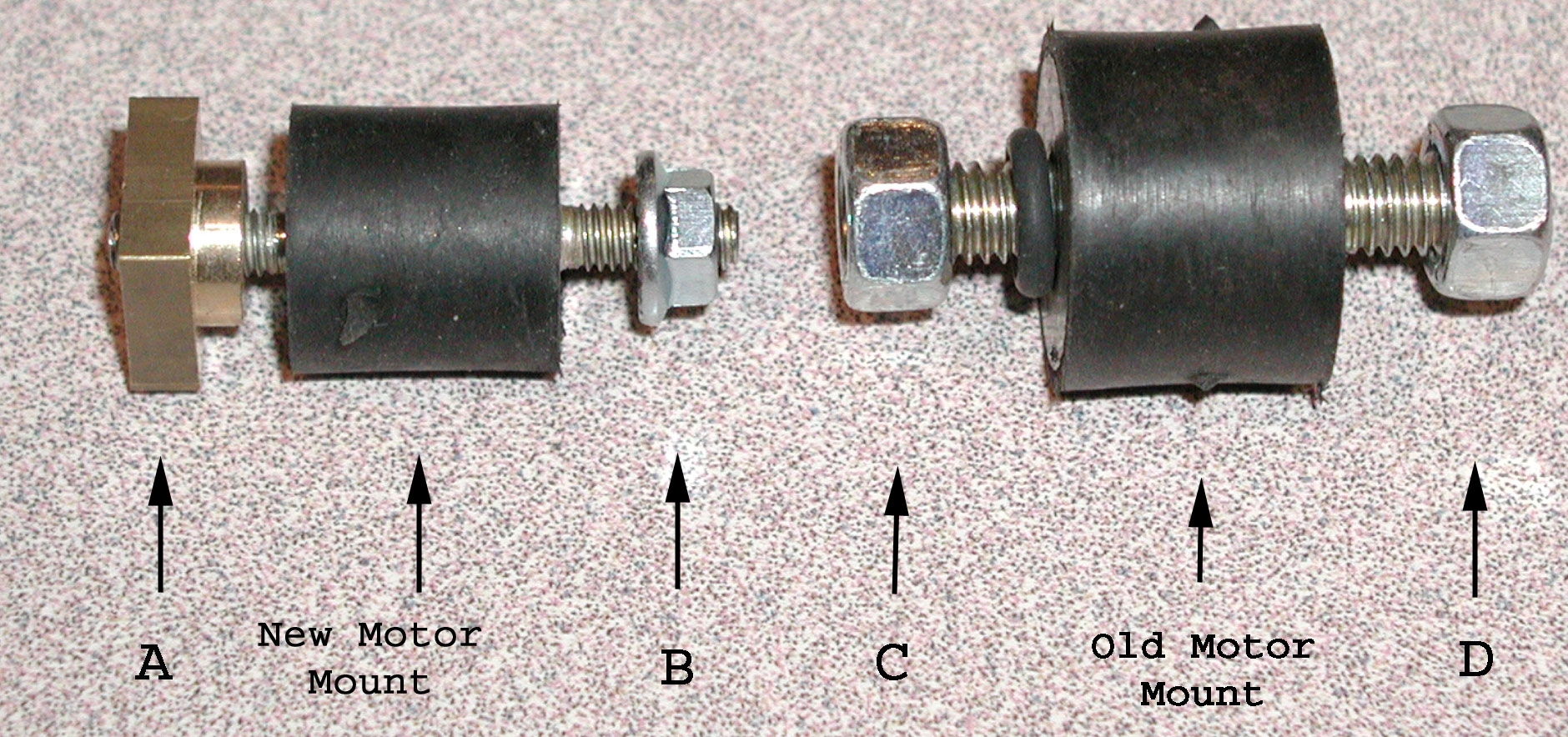
Picture 4 - Motor Mount View
1) When you need to lift and/or move the motor E)forward in the steps below, do so by actually holding the motor. Don't lift using the cylindrical part attached to the top of the motor shown with the black letter (A) on the end. 2) Only the right side pair of motor mount nuts are shown as (C) and (D) in the photo on the left. You can see by the proximity to the steam boiler to its right why you want the unit completely cool when performing the following steps! |
|
|
| Note: References to right and left below are from the perspective of facing the back side of the S1.
The old motor mount is shown on the right in the above photo.
The new motor mount is shown on the left side of the photo above. The rubberized mount can be installed with either threaded end up. However, brass nut (A) screws on at the base of the motor and steel bolt (B) screws on from the under side of the chassis. NOTE THAT THE CYLINDRICAL PART OF BOLT (A) GOES THROUGH THE MOUNTING HOLE ON THE MOTOR BASE. At this point the motor is completely free. The wire bundle and two flexible water hoses allow for plenty of movement to aid installation of the new motor mounts. Note: Steps 2 - 6, below, are performed from the front of the S1, all other steps are performed from the rear.
You're done. Double check that you didn't pinch any wires under the motor mounts and reassemble the unit in the reverse order shown above. Be amazed by the quiet. |
|